Like several other model railroaders, I had
dreamed of a large Civil War layout in HO........ until SMR introduced O scale 1800's locomotives and rolling stock. Initially I resisted the General in O, because I had a couple of Generals in HO from childhood (earlier childhood). However, when Dave Schneider later came out with a red Canasta of Masons I was smoked out. These locomotives are works of art. I think the 2 rail versions should get the same details as far as sound and smoke as the 3 rail offerings, but that has not happened yet.
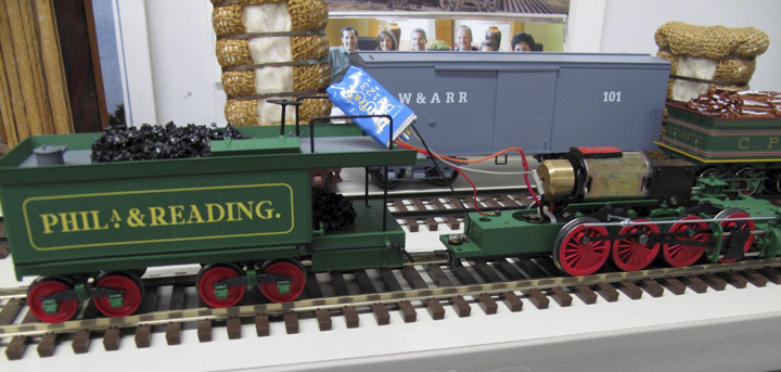
My old HO layout was block control with a homemade half-wave rectifier for incredible slow speed control, but I always dreamed of DCC. After talking with Dave, I wired the "Atlantic" with a Digitrax DH 123 mobile decoder. The motor is in the tender and there is room for the decoder as well. A few precautions are in order so as not to duplicate my mistakes. Do not remove the insulating plastic (rubber) tube from the tender pin holding the drawbar or there will be a dead short, a few sparks, and a little smoke. A small two pin plug connects the pick-ups in the engine to the tender. Dave has told me that in some cases the red and black wires from the engine were inadvertently reversed at final assembly. In those cases the plug was painted the correct color to match the tender wire. The DH 123 which is usually an HO size decoder works fine.
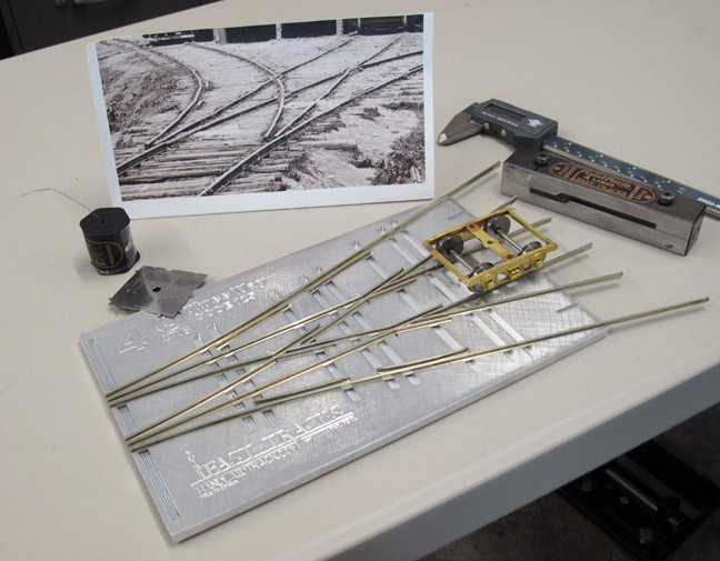
About the same time I discovered SMR I also began following FastTracks' efforts for handmade turnouts and track. Hoping I could use smaller radii, I ordered a custom assembly fixture for 21.5 and 25.5" radius track in code 125. Enough track was made for a small test layout before I committed to a layout of the entire South.
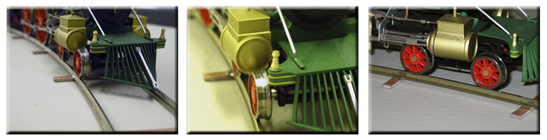
The test on 25.5" radius was OK, but tight. The 21.5" radius track is just too tight for these locomotives. Two of the movies below and some photos (above) show that the drivers bind and the lead pilot flange encounters the steam cylinder causing it to track badly and be inside the turnout point and derail on a 'thrown' turnout.
So back to the drawing board for the big layout. I will probably use the 21.5" track for a small streetcar layout for my Grandchildren.
The next test will be with 30" and 34" radii.
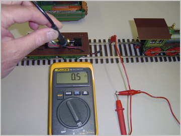
On a 60" section of straight track the Atlantic was tested pushing an empty boxcar, flatcar, and an extra truck.
A 2% grade was created with significant wheel slip (see movie). I did not test in forward direction.
SMR "Atlantic" with boxcar, flatcar, and extra truck; FastTrack O 125 track; table with 40" leg separation and one end elevated 0.805" (3/4" plywood + .055" PC board tie) for 2% grade. Have not tested in forward direction.
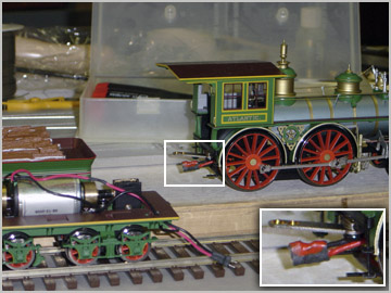
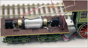
Wiring the Atlantic
The tender shell is held by 4 small screws from its
underside. Notice the electrical plug on the engine has been repainted at the factory to reflect the real polarity of its wires (see inset).
The polarity of the fireman's rail is determined to be the black tender wire.
Two leads into the decoder and two out to the motor.
Decoder is held in position with foam tape.
Received the 30/34" fixture for code 125 curved track yesterday from FastTracks, made a 200º arc of
track last night and tested the Atlantic DCC and the 0-8-0 Camel DC today. Both engines ran well, so
I will use 30" for my smallest radius of curvature. I will try to convert the Camel to DCC if possible.
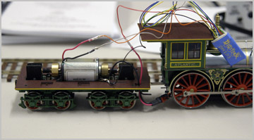
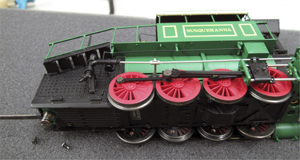
Wiring The Winans Camel "Susquehanna"With A Digitrax DH 123 Mobile Decoder
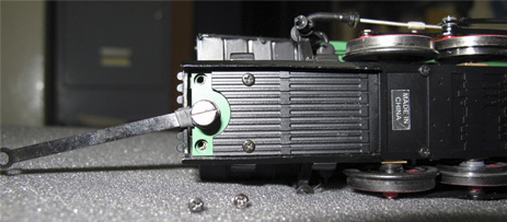
#1 - The tender acts as the fireman's rail electrical pickup. This passes thru the insulated drawbar to one of the motor leads. The tender is uncoupled and the engine placed on its side on soft foam. Two screws are removed from the firebox end and one larger screw removed from the smokebox end and then the side pipes are gently sprung to separate the superstructure from the base.
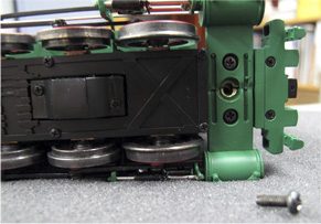
#2 - Remove two small screws underneath at the very end of the base.
#3 - Remove one larger screw at the
cylinder saddle.
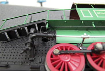
#4 - Gently elastically bend the silver piping at the firebox end or probably more easily
at the cylinder end to free the silver piping from the base. The piping is not soldered into
the connections. There is a slip fit only.
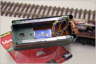
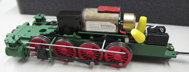
#5 - With the base separated, wiring is accessible.
#6 - Power input leads to the decoder are soldered to the insulated lug from the drawbar and the lug grounded to the engine frame. Power output leads are soldered to the motor leads and protected with shrink tubing. The Susquehanna is a wonderfully slow engine compared to the Mason Atlantic.
FastTracks' Tim Warris and company built a custom 3-way stub switch fixture for O Scale code 125 rail. The fixture is perfect as are all of their track building aids. This is a photo of a 3-way stub switch from the ACW era and my #4 3-way stub fixture. I have cut the rail and soldered the frogs and tested with an SMR truck. Even trying to guard against it, there is a tendency for the wing to roll slightly out as the wing is acutely bent after notching the base of the rail to the web. I think the twist arises from the fact that the head of the rail is not notched. To correct the twist, I use two pair of pliers to gently straighten the wing. The movie below shows all three tracks rolling freely.
Since the design of my layout is basically predicated on SMR's engines, the frogs must be powered because the length of two dead frogs on a divergent route exceeds the wheelbase of the engine or the tender for the Camels that Dave Schneider originally launched. The Camels have a relatively limited electrical pickup with only one side of the engine and the opposite side of the tender contributing.
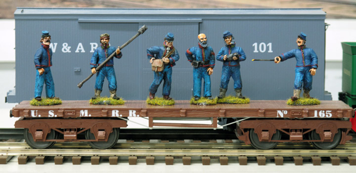
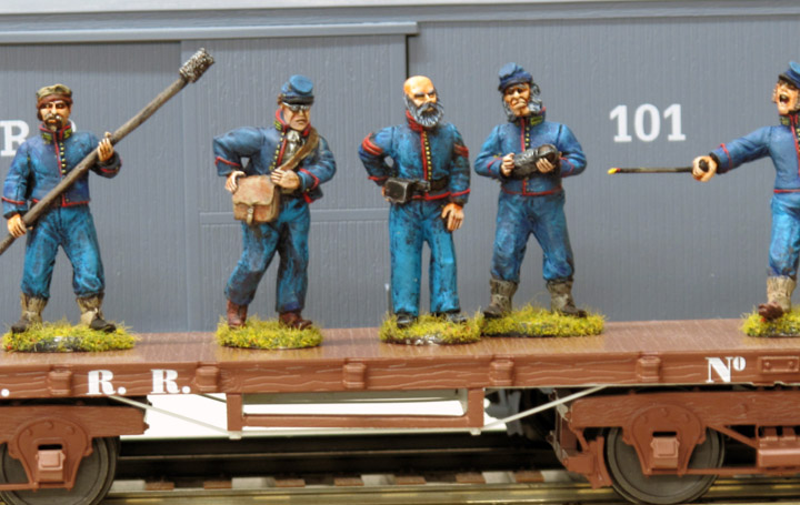
My Nephew, Will, is painting figures for the layout. He starts with Sash and Saber 40 mm ACW castings and with a multi coat process and detailed handwork ends up with exquisite and accurate soldiers, in this case a Federal Artillery Crew. Canon, wagons, horses, and many Confederates are coming soon.
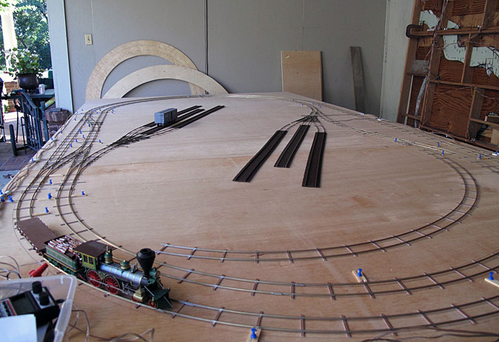
The old HO layout is standing on end. The trial O layout (approx. 74 x 144") is on sawhorses in the carport. Notice the large protractors leaning against the far wall. These have been used to cut the curves to correct arc. This layout features 30 and 34" radii, two crossovers, and two 3-way stub switches. The track is held in place with pushpins and scrap wood ties. There are no reversing sections and the frogs are not powered yet. Track is provisionally surface wired with speaker wires soldered to track connectors. Unbelievably there were no shorts with the assembled layout. The locomotive is wired for DCC and I use only the HO voltage setting on the Digitrax system.
The trains will be run thoroughly on the layout to identify any problems with the turnouts. One turnout needs one point filed slightly. At this stage any section of track can be easily removed and repaired or replaced. Once happy with the track, I will mark the exact position of the PC board ties in several locations for later final assembly. I have not decided if there will be 'negative spaces' on this layout (gullies and valleys) or if I will just experiment with hills and cuts. There is no question that the most realistic scenes have negative and positive relief with the train snaking its way around.
All in all the Atlantic has been run very little since I bought it from SMR. On trial runs there is a squeak that hopefully will respond to a little oil.