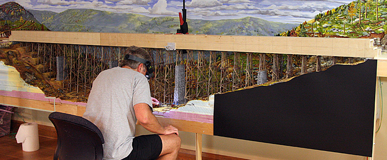
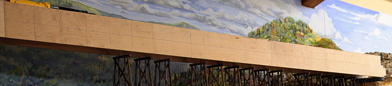
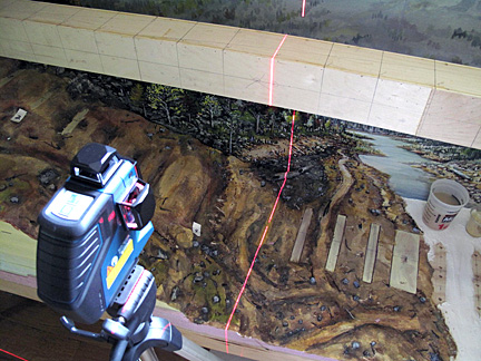
The first was the plywood box-temporary bridge-ledger board. It was constructed in the shape of a square-A and spanned the entire 13 foot valley sitting in mortised stop-blocks at each end. Once the number of bents was decided, the length of the box was evenly divided and marked on two adjoining surfaces. These division lines were ‘dropped’ to the valley below using a machinist square initially and later more accurately with a 3-D laser.

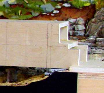
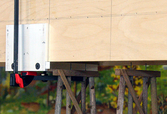
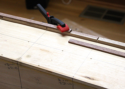
Harold fabricated the clamp which consisted of two aluminum plates in an L-shape with a bar underneath which would tighten down securing the top beam of a bent when it was inserted.
The clamp itself was secured to the box-guide with its right edge aligned with the mark of a bent's location on the layout. Two slots were milled into the main plate to accept the steel pins at the top of each bent.
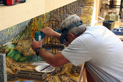
Holes were drilled in the plywood footers set into the insulation foam and the particular bent was cut to length.
The bent's top beam and its pins were then inserted into the clamp with the bent's feet sitting in the drilled holes. Five-minute epoxy was dropped into the holes while the whole box-guide and attached bent was lifted at one end, pivoting on the opposite end which remained in place in the mortised end-block.
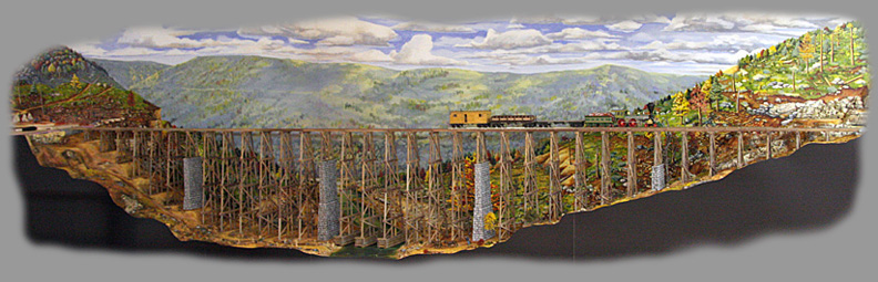
The box-guide was lowered and the bent landed in its forever-home - a happy bent.
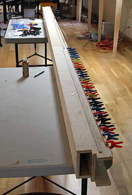
The box-guide was laid on its side and the "sandwich" was glued-up using the guide's pin location marks.
WHAT A SYSTEM!
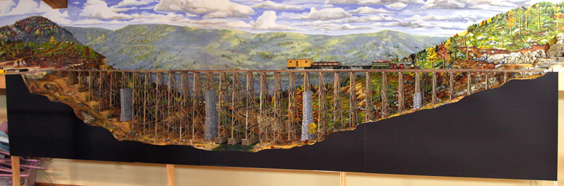
The primary structure was in place, however, and celebratory toasts ensued.